An air compressor is a versatile device used in various industries for generating compressed air. It is important to understand the basic structure of an air compressor to effectively operate and maintain it. This knowledge also aids in troubleshooting and optimizing performance. In this article, we will explore the fundamental components that make up the basic structure of an air compressor.
The Basic Surcture of Oil Injection Screw Air Compressor
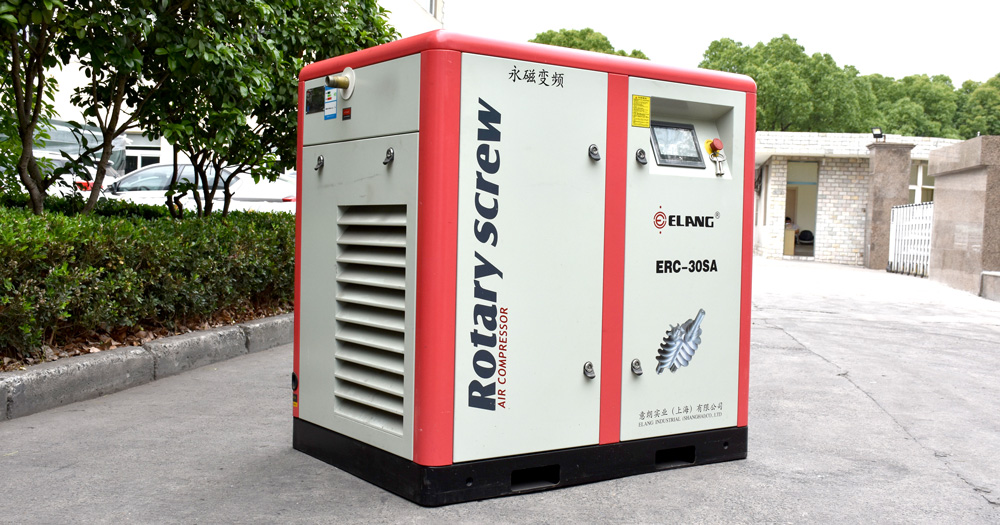
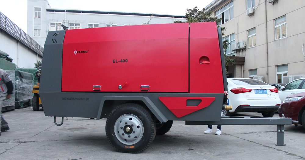
Elang oil injection screw air compressors can be classified into two types: stationary and portable, and the main structures are essentially the same. The body of Oil injection screw air compressor does not have a cooling water system. The rotor is an integral structure without internal cooling. The radial and axial forces generated by compressed air are borne by rolling bearings. There is a simple shaft seal between the working section of the rotor at the exhaust end and the bearing. This seal is achieved by creating grooves on the casing or shaft and supplying sealing oil under certain pressure. In addition, there is no synchronous gear in the oil injection screw air compressor, and usually there is no volume flow control or compression ratio control slide valves.
Usually, the small gear of the oil injection screw air compressor is directly installed on the rotor shaft, and the large gear can be installed on another shaft supported by bearings at both ends, or directly on the end of the motor shaft.
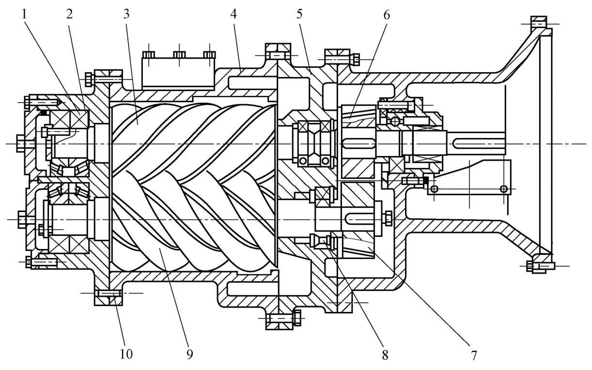
The main structure of an oil-injected screw air compressor
The compressor adopts internally mounted speed increasing gear to drive the male rotor. The compressors with different volume flow rates can be easily obtained by using different speed increasing gears. At the outlet end of the rotor, single-row tapered roller bearings installed face-to-face are used to bear the radial force and axial force in the compressor at the same time, and position the rotor in both directions. The body of the compressor consists of three parts: an inlet end cap, a cylinder, and an outlet end cap. There is an axial suction port on the inlet end cap, while a buffering space is designed at the radial suction port on the cylinder. At the same time, axial and radial suction ports are positioned on the outlet end cap and cylinder. Additionally, there is a reliable oil-lubricated mechanical seal at the shaft extension.
The Basic Surcture of Oil Free Screw Air Compressor
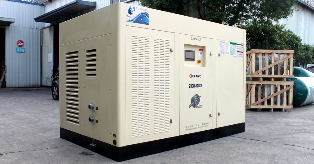
Elang oil free screw air compressors have a more complex structure compared to Elang oil injection compressors.
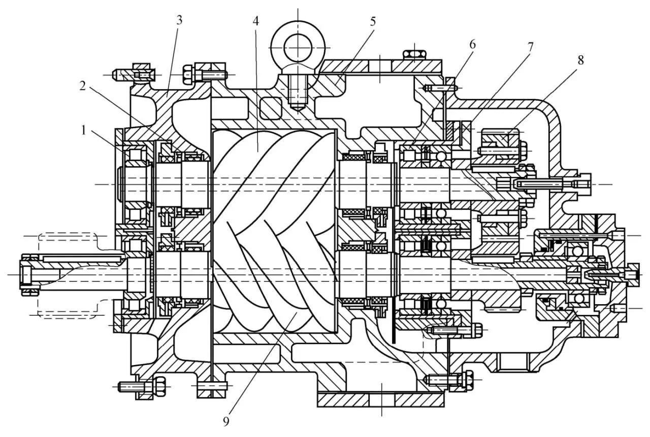
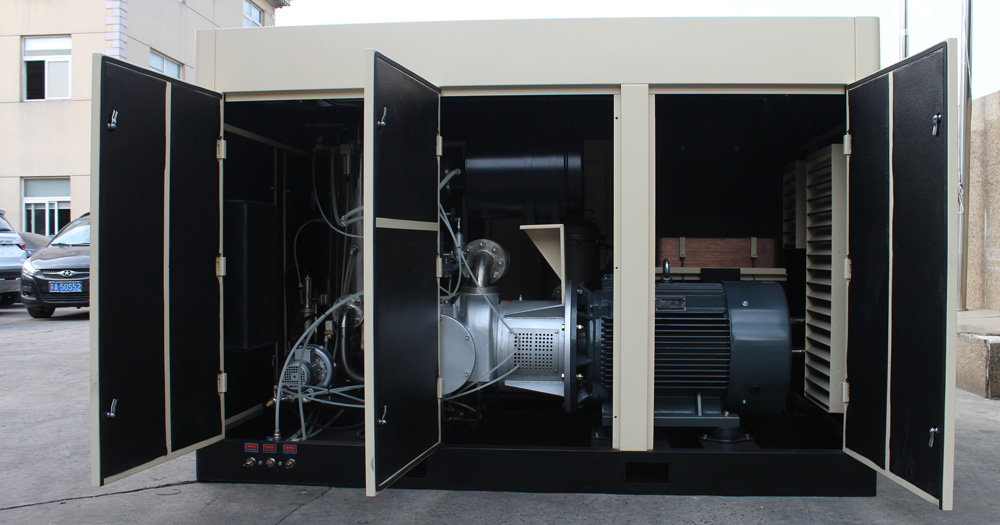
The main structure of an oil free screw air compressor
The rotors of Elang oil free air compressor can’t come into direct contact with each other. Therefore, the male rotor is driven by the female rotor through highly precision synchronous gears. The synchronous gears on the female rotor are adjustable to ensure the optimal meshing clearance between the rotors. In order to reduce the uneven deformation of the rotor caused by thermal expansion, the center of the rotors are cooled by circulating oil for cooling. Considering the small load of general air compressors, both the radial and thrust bearings adopt rolling bearings to accurately position the rotor. Graphite ring seals, compressed by corrugated springs, are utilized on both the suction and discharge sides to isolate the compression chamber and the bearing parts. Additionally, to prevent compressed air from entering the bearings and affecting the lubrication, a vent hole is opened on the body between the last sealing unit to release any leaked air.
