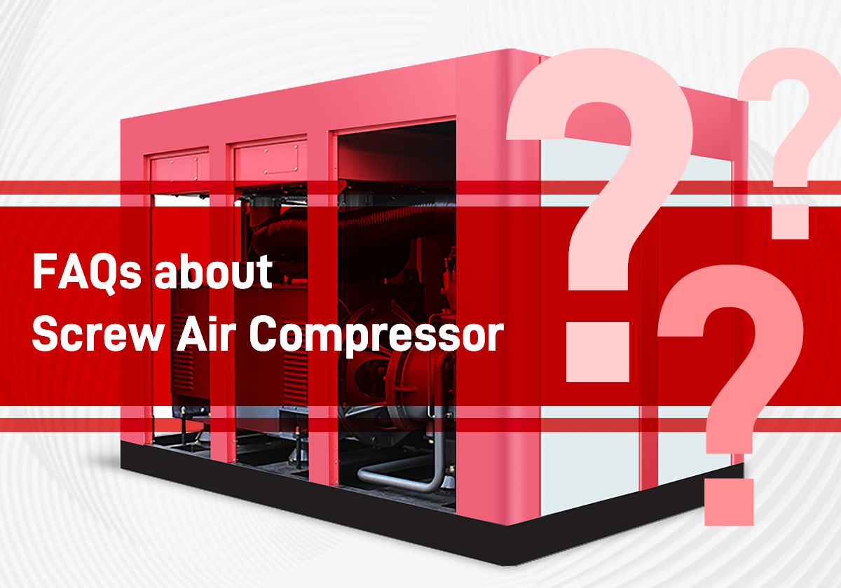
In our conversations with customers, we are well aware that they may encounter various problems and confusion when selecting, using, and maintaining screw air compressors. In order to provide better support and assistance to you, we have compiled a complete set of common technical questions and answers, hoping to solve your doubts and provide guidance.

Firstly, when the air compressor is in unloaded state, the inlet valve is closed to ensure enough air enters the compressor, establishing lubricating oil pressure to ensure stable rotor operation.
Secondly, when the air compressor is in loaded state, the inlet valve closes, and pressure is released through the small hole to ensure smooth closure of the swing check valve.
1. Four factors that affect the formation of carbon deposits:

  1. Air filtration. Dust particles carried in with the air intake thicken the oil, increasing the time of oil oxidation reaction, thus accelerating the formation of carbon deposits. Therefore, it is necessary to pay attention to the correct installation of the air filter, and if any damage is found during cleaning, it must be replaced.
  2. Temperature. Different grades and types of lubricating oil have different initial oxidation temperatures. Long term operation of air compressors in high-temperature areas will accelerate the oxidation of lubricating oil. For compressors equipped with water coolers, it is recommended to use treated or impurity-free cooling water to prevent blockage of the water passages.
  3. Lubricating oil quality. The lubricating oil provided by air compressor manufacturers usually does not accumulate carbon within the specified service life. Currently, there are many procurement channels for lubricating oil, and its quality may inevitably vary. Some users use alternative oils, and carbon deposits is not uncommon in such cases.
  4. Lubricating oil is used beyond its expiration date. If the lubricating oil continues to be used after exceeding the specified service life, the air compressor will be unable to operate in a short period of time due to carbon deposits.

2. Method for cleaning carbon deposits on the air end: For carbon deposits in the oil circuit and air end, specialized cleaning agents (carbon deposit remover or bearing cleaner) can be used. Cleaning can also be performed without disassembling the air end. For small air ends, they can be directly placed in a container for soaking, and during soaking, the rotor should be rotated several times. For large air ends, after closing the outlet and oil pipelines, the cleaning agent can be poured in for soaking. The soaking time should be determined according to the instructions of the cleaning agent, generally 8 to 12 hours. For some cleaning agents with strong corrosiveness, the soaking time specified by them should be strictly followed. After soaking, rinse with pressurized water, and then blow dry with compressed air.

In summer, the weather is hot, and the appearance of lubricating oil may become slightly diluted; in winter, the weather is cold, and the appearance of lubricating oil may become slightly thicker. Customers use 46# or even 68# lubricating oil in summer, and 32# lubricating oil in winter, because they did not consider that the obvious difference in the appearance of lubricating oil only exists in low-temperature conditions, and this variation becomes very small when the lubricating oil operates in the air compressor at high temperatures. Therefore, the performance of lubricating oil in terms of lubrication is not related to viscosity index. At the same time, lubricating oil adopts modern advanced blending technology, where the base oil film only serves as a carrier for additives, and lubrication is completed by additives. Therefore, simply changing lubricating oil with different viscosity indexes does not have any practical effect.
It is generally believed that the ignition accidents of oil-lubricated air compressors are caused by carbon deposits. When designed according to standards, the whole pressure system of the compressor should be clean and free of carbon deposits, reducing the risk of ignition accidents. For pressure systems that generate carbon deposits, the grade of oil is important, and regular cleaning of the pressure system is equally important.
It has been verified that good design, lubrication, and maintenance can prevent ignition accidents in oil-injected rotary compressors. One of the recognized causes of ignition is the failure of the cooling system, resulting in a rapid increase in exhaust temperature exceeding the normal temperature of the compressor. One of the recognized causes of ignition is the failure of the cooling system, resulting in a rapid increase in exhaust temperature exceeding the normal temperature of the compressor. When the carbon deposition layer in the hot zone increases sufficiently thick, it triggers a fire. In addition, damage to the temperature control valve can also increase the exhaust temperature, leading to accidents.
Additionally, abnormal temperature increases caused by clogged oil filter core can accelerate oil oxidation and also pose a risk of fire. The three important factors to prevent oil ignition hazards are: ① reasonable design; ② Proper selection of oil; ③ Operation and maintenance of compressors. The following points are particularly important: maintaining low fuel consumption, regularly changing oil, and ensuring the normal operation of the oil cooling system.
In many companies, after over 1 year of use, screw air compressors will leak or seep oil in multiple parts. The main oil leakage parts include the sealing surface of the air end, oil-gas tank, and their pipelines. The oil leakage points on the air end include shaft seals, end caps, oil pipe joints, pressure relief valves, and other parts. The oil leakage points on the oil-gas tank include oil pipe joints, oil pipes, oil level mirrors, oil-gas tank covers, expansion joints, air hoses, etc.
There is no absolute boundary between light repair, medium repair and overhaul of screw air compressor, and the specific situation of each using unit is different.

  1. Check the carbon deposits on the rotor;
  2. Check the intake valve servo cylinder diaphragm;
  3. Check and tighten the screws in various parts;
  4. Clean the air filter;
  5. Solve the problems of air compressor and pipeline leakage and oil seepage;
  6. Clean the cooler and replace the faulty valve;
  7. Inspect the safety valve and pressure gauge.

In addition to do a good job of all light repairs, it is also necessary to dismantle, repair, and replace some parts of the machine, such as dismantling the oil-gas tank, replacing the oil filter and oil-gas separator, checking the wear of the rotor, inspecting and adjusting the thermal control valve and pressure maintenance valve to restore normal operation of the machine.

Equipment Specifications
Project Unit Technical Parameter
Model
Rated Displacement m3/min
Rated exhaust pressure MPa
Motor Speed r/min
Shaft Power kW
Spare Parts and Materials Required for Maintenance
Spare parts bearings, oil seals, O-rings, shaft sleeves, carbon cleaning agents, and oil pipes that need to be replaced
Materials sealant, calico, lead tetroxide, machine cleaning cloth, sandpaper (# 0, # 1, # 2), gasoline or kerosene
Tools
ring wrench, hex key, socket wrench, pipe wrench, copper rod, feeler gauge, hydraulic puller (self-made fixing plate), lifting shackle, steel wire rope, and pin puller (self-made)
Safety Notes
1. Take anti slip measures on site, avoid open flames when using gasoline, and use special tools to disassemble bearings;
2. When disassembling the male and female rotors, be careful to pull gently to prevent damage to the rotor;
3. After disassembling the male and female rotors, place them horizontally to prevent damage;
4. When reinstalling, use compressed air to clear and inspect the oil circuits of each part of the machine to prevent foreign objects;
5. When disassembling the gearbox, pay attention to lifting slowly to prevent gear damage.
Process 0: Preparation work before maintenance
1.Understand the existing defects of the equipment and conduct pre repair identification;
2.Prepare to replace the wearing parts and tools for maintenance, lifting, cleaning;
3.Apply for maintenance work tickets.Process 1: disassembly
1. Contact the thermal process engineer to inspect each instrument and remove the instruments connected to the main body;
2. Drain all the lubricating oil inside the machine body;
3. Remove the air filter;
4. Remove the intake valve;
5. Remove cooling water pipes, oil pipes, measuring points and other fittings;
6. Remove the protector flywheel cover or flywheel V-belt;
7. Remove the motor anchor bolts;
8. Hang the machine body with a hoist, remove its anchor bolts, and lift it out.The following work is carried out in a clean maintenance site:
1. Rotate the rotor, inspect the appearance and wear of the male and female rotors, measure the axial and radial clearance between the male and female rotors and the machine body.
2. Remove the axle.
3. Remove the inlet end cover. Some models have a speed increasing gear mechanism. At this time, the gearbox should be removed;
4. Remove the inlet end cover and prepare to inspect and disassemble the bearings;
5. Remove the bearing bracket at the inlet end;
6. Install a puller at the exit end, separate the male and female rotors from the outlet end bearings, apply gentle force during disassembly, and rotate the rotor;
7. Take out the male and female rotors in sequence.

Process 2: inspection and repair stage
1. Cleaning of spare parts
1.1.The disassembled parts should be cleaned in kerosene or carbon cleaning agent to remove carbon deposits and rust on them;
1.2.Clean and unclog the machine body and oil pipelines;
1.3.Clean and unclog the cooling water pipes and cylinder cooling water chamber.

2. Maintenance of male and female rotors
2.1. Check the surface wear of the male and female rotors for any peeling, gouges, knots and cracks.
2.2.Polish the surface defects of the rotor by first using a mixed file or irregular file, and then polishing with # 500 sandpaper.
2.3. The serious damage to the rotor caused by untimely overhaul of the air compressor or odor in the body will make it impossible to repair the rotor.

3. Maintenance of the machine body
Check the wear and tear of the machine body, whether there are cracks, rust scars, burrs, nicks, grooves, etc. If there are any such phenomena, repair them.

4. Gear box maintenance
4.1. Check whether the fitting traces of the male and female gears meet the requirements;
4.2. Check the wear of the male and female gears. If there are cracks or broken teeth, replace the gears with new ones.

5. Bearings maintenance
Screw air compressors have small clearance and strict requirements for bearings. During major repairs or troubleshooting, all bearings are required to be replaced. Use original spare parts or bearings of the same model for bearings.

6. Maintenance of shaft seal
The screw air compressor overhaul requires the replacement of a new shaft seal. The shaft seal replacement process is simple, but a slight negligence during assembly will cause oil leakage from the shaft seal during operation. The shaft seal requires the use of original spare parts.

The following work should be done before assembly:

  1. The compressor air end and accessory equipment should be cleaned and all cleaning agents or moisture should be removed. The rotor, bearings, gears, and cylinders should be carefully checked for damage and other defects to prevent impurities from entering the working chamber.
  2. The cylinders and rotors of the compressor should undergo a tightness test according to the pressure specified in the equipment technical documents. The assembly of cylinders, rotors, and gears should meet the following requirements: the longitudinal and transverse waviness of the cylinder should not exceed 0.05/1000, and their inclination should be in the same direction. Measurements can be taken on the midplane of the cylinder or inside the bearing hole.

Process 3: assemble
1. After the maintenance of air compressor spare parts is normal and the spare parts are ready, the air compressor can be reinstalled. During the installation process, be careful to prevent foreign objects from falling into the body of the air compressor.
2. The male and female rotors of the air compressor have been installed successively, and can be installed horizontally or vertically.
3. Install the imported bearing seat, ensuring that the sealant is evenly applied and not too thick. After installation, measure the total axial clearance.
4. The bearing position at the outlet of the male and female rotors is equipped with axial positioning plates. If the positioning plates are checked for wear and the radial clearance measurements of the shaft are normal before disassembling the air compressor, the positioning plates can be reinstalled directly.
5. Install the inlet and outlet bearings sequentially according to the original position of the bearings. When installing bearings, control the heating temperature between 90 and 120 ℃. When installing bearings, pay attention to cooling one bearing before installing the other.
6. Lock the bearing locating nut.
7. Install the elastic gaskets and bearing end cover at the outlet end. Measure the inlet axial clearance between the male and female rotors and the machine body.
8. Measure the radial clearance between the male and female rotors and the machine body. If the clearance is normal, it indicates that the installation steps above are correct. For air compressors with abnormal rotation, lead tetroxide can be applied to detect the meshing condition of the male and female rotors.
9. Reinstall the gearbox bearings and gears. When reinstalling the gearbox, pay attention to applying the sealant evenly and not too thick.
10. When reinstalling the air compressor shaft seal, pay attention to applying lubricating oil to ensure smooth installation. Apply a small amount of sealant to the dynamic and static parts of the shaft seal.
11. Reinstall the coupling and complete the installation of the air end.

Quality Standard
1. Measurement method for fitting clearance of air compressors
The fitting clearance of the air compressor air end includes the radial fitting clearance between the outer circle of the male and female rotors and the cylinder wall of the machine body. The axial clearance between the two end faces of the male and female rotors and the cylinder side walls includes two clearances: the outlet end and the inlet end.
The radial clearance between the male and female rotors and the body is measured using a feeler gauge at the inlet of the air compressor.
The axial clearance at the outlet end – total axial clearance of the rotor – axial clearance at the inlet end. The total axial clearance of the rotor can be measured during the installation process of the air compressor. After the installation of the male and female rotors and the end cover of the inlet end bearing, the male and female rotors are pushed back and forth axially, and then measured usding a dial gauge.
The axial clearance between the male and female rotors and the inlet end of the machine body is measured using a feeler gauge from the inlet of the air compressor. When measuring, the machine body is installed after the air compressor bearings are installed, and the elastic gasket and end cover at the outlet end are pre installed.
The meshing clearance between the male and female rotors has bearing positioning, which can be checked for friction using lead tetroxide.

2. Quality standards for fitting clearances of air compressors
The radial clearance between the male and female rotors and the machine body is 0.1mm, generally not greater than 0.1mm;
Axial clearance at the outlet end is 0.1-0.2mm;
The axial clearance at the inlet end is 0.4-0.7mm.

3. Adjustment method for rotor axial clearance
After measuring the axial clearance of the rotor of the air compressor, if it is necessary to adjust the axial clearance, a gasket should be added at the outlet end positioning plate. Generally, if the positioning plate is not significantly worn, it does not need to be adjusted. In addition, if the bearing is not installed properly or the locking force is insufficient after installation, it will cause the axial clearance at the inlet end to be too small. At this time, use a copper rod to tighten the bearing and locking nut to adjust it normally.
After aligning the cylinders and rotors, the foot bolts should be evenly tightened, and a level should be placed on the cylinder and rotor journals to check for any unevenness. When aligning the unit, the centerline of the motor shaft (or gearbox shaft) should be used as a reference, and the radial displacement should not exceed 0.05mm if not specified by the equipment technical documents.

4. Gearbox
The surface of the gear should be free of cracks, erosion, and other phenomena, and the contact between the tooth surfaces should be close to 70% along the tooth length. The meshing clearance of the gear is 0.2-0.3mm, and it should be replaced when it exceeds 0.5mm.

5. Axis bending measurement
Some faulty air compressors require measurement of shaft bending during the overhaul, which should be carried out separately the disassembly of the air compressor. The measurement method is directly based on bearing positioning on the body, and the qualified standard for shaft bending is 0.03mm.

Process 4: run-in
1. During the trial run, the air compressor pressure and current should remain within the operating range without significant fluctuations, and the vibration of each part should not exceed 0.1mm.
2. The bearing temperature should not exceed 80°C, and the oil temperature should not exceed 60°C.
3. The shaft seal should have no oil leakage or seepage.
4. After the overhaul, the screw air compressor often experiences excessive vibration (about 0.1mm) during trial operation. Due to the automatic adjustment and compensation function of the elastic gasket at the outlet of the air compressor, after a period of operation, the rotor clearance is adjusted appropriately, and the vibration is automatically eliminated.
5. Apply for the termination of work permit.

When the pressure drop across the oil-gas separation filter exceeds 0.08MPa, the compressor should be stopped for replacing the oil-gas separation filter (different brands of air compressors may have different settings). This is because the compressor’s unloading is sampled based on the pressure after separation. If the unloading pressure is set to the rated pressure, the actual load on the motor is the rated pressure plus a pressure difference of 0.08MPa. The motor may be overloaded as a result.
In air compressors with the same operating time, the service life of air filters varies due to differences in working environments and operational statuses.
If the working environment of the air compressor is humid with a lot of dust, the air filter will quickly become clogged. If the air filter of the air compressor is damaged during installation, transportation, or cleaning but continues to be used, the oil filter of the air compressor will soon become clogged. Additionally, The working environment temperature of the air compressor is high, and due to equipment reasons or failure to switch the air compressor in a timely manner, the air compressor will be shut down for a long time (such as about a month), which will cause the adhesive particles on the oil filter or oil-gas separator to dry up, block the filtering holes, and shorten the service life of the filters.Therefore, relying on running time as an unique standard for replacing the filters may lead to problems such as delayed replacement or waste.

Top 10 most-read technical articles

  1. Common Technical Questions About Screw Air Compressors-How to Select an Air Compressor for PET Bottle Blowing Machine?
  2. Common Technical Questions About Screw Air Compressors-1Analysis and Solution for Frequent Loading and Unloading of Air Compressor
  3. Common Technical Questions About Screw Air Compressors-2Exploring The Repair and Maintenance of Screw Air Compressors
  4. How does a Rotary Screw Air Compressor Work?
  5. 7 Tips for Choosing The Right Air Compressor
  6. How to Design a Compressor Room?
  7. Working Principle and Application of Oil Free Scroll Air Compressor
  8. Screw Air Compressor Troubleshooting Guide
  9. How to Design a Compressed Air System?
  10. How to Prevent Surge in Centrifugal Compressors?

Good News: We’ve set up a knowledge base offering more detailed information on the working principles, maintenance methods, and applications of screw air compressors. Click HERE to learn more!