Serch the Knowledge Base
04. What are The Functions of The Main Components of The Oil System in A Screw Air Compressor Unit?
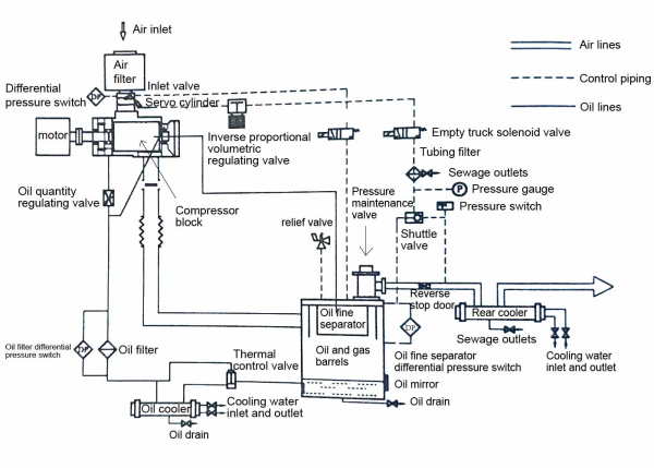
- Temperature Control Valve: There is a temperature control valve at the front of the oil cooler. Its function is to regulate the oil temperature to maintain the exhaust temperature above the dew point temperature in an oil oil cooler system. When the compressor is just started, the temperature of the machine is low. At this time, the temperature control valve will automatically open the return circuit, and the oil will enter the body without passing through the oil cooler. If the lubricating oil temperature rises to 67°C or higher, the temperature control valve gradually opens, and at 72°C, it fully opens. At this point, all the oil flows through the oil cooler for cooling before re-entering the body.
- Oil Cooler: Its function is to cool the high-temperature lubricating oil that has been separated from the oil and gas mixture in the oil-gas separator. After the separation process, the lubricating oil is free from air. The oil cooler cools down this oil to reduce its temperature. Once the lubricating oil is cooled, it is then directed back into the air compressor for further use.
- Oil Filter: It is to filter out impurities and contaminants from the lubricating oil in the oil system, to maintain the cleanliness and optimal performance of the lubricanting oil.
- Oil-gas Separator: It has two main purposes: storing lubricating oil and performing the initial separation of oil and gas. The function of the oil-gas separator (oil-gas bucket) has two main purposes: storing lubricating oil and performing the initial separation of oil and gas.
The oil-gas separator, commonly referred to as the oil-gas bucket, is equipped with an oil level sight glass on the side. Before each startup, it is essential to ensure that the static level of lubricating oil inside the oil-gas bucket is between the high and low oil level marks indicated by the sight glass. A drain valve is installed at the bottom of the bucket. Its function is to store lubricating oil and perform the initial separation of oil and gas in the mixed gas. When the mixed gas of oil and gas is introduced into the oil-gas bucket, the special structure of the bucket reduces the flow velocity of the mixture, facilitating the first separation of oil and gas. - Fine Oil Separator: The fine oil separator is made of multi-layered fine fibers. It can effectively filter out the mist-like oil and gas contained in the compressed air during the 2nd oil-gas separation stage. After filtration, the oil content in the compressed air is lower than 3ppm. The filtered oil is collected in the groove at the bottom of the fine oil separator and then returned to the bearing end of the equipment through the return oil pipe, preventing the filtered lubricating oil from being discharged with the air .
The outlet of the fine oil separator is equipped with safety valves, discharge valves, and pressure maintenance valves. Compressed air is led out through this outlet and directed to the rear cooler for cooling. - Expansion Joint: The function of an expansion joint is to eliminate the internal stress caused by thermal expansion in pipelines and the vibrations in the system.
- Oil Cut-off Solenoid Valve: It is to close the lubricating oil inlet during shutdown, preventing the lubricating oil under pressure from entering the air end, and also to prevent lubricating oil from spraying out from the air end inlet.

Detailed Diagram of 55 -180 kw Screw Air Compressor System
