-
1. Basic knowledge
- 01. What is an Air Compressor and What are Its Uses?
- 02. How are Air Compressors Classified?
- 03. What is The Working Principle of a Screw Air Compressor?
- 04. What are The Advantages and Disadvantages of Screw Air Compressors Compared with Other Types of Air Compressors?
- 05. What are The Main Technical Parameters of The Screw Air Compressor?
- 06. What are The Differences Between Twin-screw Air Compressors And Single-screw Air Compressors?
- 07. What are The Advantages of Oil-injected Screw Air Compressors?
- 08. What are The Tooth Profile Characteristics of a Twin-screw Air Compressor?
- 09. How to Control The Fuel Injection Volume of The Screw Air Compressor?
- 10. What is The load Factor of an Air Compressor?
- 11. What are The Cooling Methods of Compressed Air?
- 12. What are The Effects of Altitude on Air Compressors?
- 13. What are The Effects of Altitude on Air Compressor Engineering?
- 14. What is The Volumetric Flow Rate of A Screw Air Compressor?
- 15. What is The Clearance Volume of a Screw Air Compressor?
- 16. What is The Compression and Compression Ratio of A Screw-type Air Compressor?
- 17. How to Express The Fuel Consumption of Screw Air Compressors?
- 18. Calculate The Fuel Consumption of An ERC-120SA/7kg Air Compressor with 16.2m3/min Air Delivery
- 19. What is The Volumetric Efficiency, Compression Efficiency and Mechanical Efficiency of A Screw Air Compressor?
- Show Remaining Articles ( 4 ) Collapse Articles
-
2. Air Compressor Components
- 01. What is The Structure of A Screw Air Compressor?
- 02. What are The Components of A Screw Compressor? What are The Main Equipment?
- 03. What are The Functions of The Main Components of The Air Flow System in A Screw Air Compressor Unit?
- 04. What are The Functions of The Main Components of The Oil System in A Screw Air Compressor Unit?
- 05. Where is The Check Valve of The Screw Air Compressor Installed? What is Its Function?
- 06. What are The Types of Intake Valves for Screw Compressors?
- 07. What is The Function of The Inverse Proportional Valve in a Screw Air Compressor? How to Adjust?
- 08. What is The Function of The Small Hole Machining for The Screw Air Compressor Intake Butterfly Valve Core?
- 09. How Does The Intake Valve Work in A Screw Air Compressor?
- 10. What is The Function of The Servo Cylinder for The Intake Valve?
- 11. What are The Techniques for Separating The Oil and Gas Mixture in An Air Compressor?
- 12. What is The Working Principle of The Oil-gas Separation?
- 13. How to Select The Oil Fine Separator for A Screw Compressor?
- 14. What are The Types of Safety Valve?
- 15. What is an Air Filter and How does It Work?
- 16. What are The Characteristics of Common Air Filters?
- 17. What should be Noted When Installing an Air Filter?
- 18. What are The Characteristics and Working Principle of Glass Fiber Material in Filtration?
- 19. Why do Coalescing Filter Elements Use a Porous Foam Layer?
- 20. What are The Classification Standards for Air Filter Elements and What are The Applications for Different Grades?
- 21. Why do Air Filters Need to be Used in Combination?
- 22. Do Air Filters Reduce the Air Dew Point?
- 23. What is The Relationship Between Air Filter Efficiency and Air Temperature?
- 24. What are The Accessories of Air Filters and What are They Used for?
- 25. What are The Three Main Pneumatic Components?
- 26. What is The Structure, Function, and Working Principle of The Gas-Water Separator?
- 27. What are The Main Performance Indicators of The Gas-water Separator?
- 28. What are The Compressed Air Treatment Equipments?
- 29. How Many Types of Transmission are available for air compressors?
- 30. What are The Differences between Direct Drive and Belt Drive in Compressor?
- 31. What are The Two Cooling Systems of Air Compressor? And What is The Difference?
- 32. What is The Cooling Temperature Difference of The Cooler?
- 33. What are The Main Sources of Noise in A Screw-type Air Compressor?
- Show Remaining Articles ( 18 ) Collapse Articles
-
3. Control System
- 01. What are The Protective Control Measures for Screw-type Air Compressors?
- 02. What is The Features of a Single-machine Controller for a Screw Air Compressor?
- 03. What are The Basic Operating Buttons and Alarm Functions on The IC Board Control Panel of The Screw Air Compressor?
- 04. What are The Functions of The Indicator Lights on The IC Board Control Panel of The Screw Air Compressor?
- 05. What are The Operational Buttons and Alarm Functions of PLC Control Panel for Screw-type Air Compressors?
- 06. What is The Startup Process and Emergency Shutdown of an Air Compressor's Motor?
- 07. What is Compressor Motor Overload Protection?
- 08. What is The Purpose of The Differential Pressure Protection Device for The Filter in a Screw Air Compressor?
- 09. What is The Function of Air Compressor Control Cabinet?
- 10. What are The Precautions for The Single Control and Joint Control Conversion Operation of The Air Compressor Control Cabinet?
- 11. What is The Relationship between The Signal of Air Compressor Empty Running for Too Long Time and The Joint Control?
- 12. What is an Air Compressor Pressure Sensor?
- 13. What is PLC and What are The Advantages of PLC Control Systems?
- 14. What is a Screw Air Compressor PLC Made of?
- 15. What is a CPU of Screw Air Compressor PLC? And What are the Components?
- 16. What are The Other Devices in The PLC System?
- 17. What is The Energy-saving Significance of Screw Air Compressors?
- 18. How can You Improve The Energy Efficiency of The Air Compressor?
- 19. What are The Impacts of Air Leakage in Compressed Air Systems on Energy Efficiency?
- 20. What are The Characteristics and Basic Principles of the Inverter?
- 21. What are the Factors Considered When Selecting an Inverter?
- 22. How to Select The Motor for an Air Compressor?
- 23. How to Match Air Compressors to Achieve Energy Saving When The Air Delivery is Known?
- 24. How to Choose The Right Screw Air Compressor?
- 25. Daily Monitoring Required When Operating an Air Compressor
- 26. Which Energy-saving Monitoring and Testing Projects Should be Conducted for Air Compressors?
- 27. What are The Methods and Requirements for Energy-saving Monitoring of Air Compressors?
- 28. How to Determine If The Pressure Drop in The Compressor System is Normal?
- 29. What are The Basic Standards for Selecting an Air Compressor? And What are The Main Issues to Pay Attention to?
- Show Remaining Articles ( 14 ) Collapse Articles
-
4. Lubrication & Sealing
-
5. Operation & Maintenance
- Articles coming soon
-
6. Test Run & Acceptance
- Articles coming soon
-
7. After Treatment Equipment
- Articles coming soon
-
8. Common Faults & Solutions
- Articles coming soon
-
9. Design Standard
- Articles coming soon
01. What is The Structure of A Screw Air Compressor?
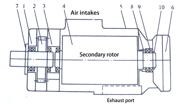
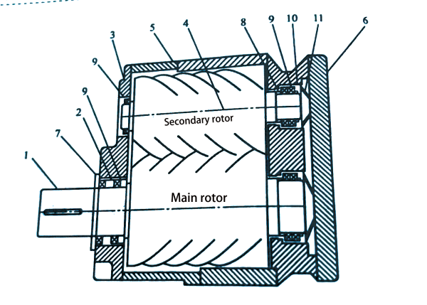
The oil-injected screw air compressor is a type of double-shaft positive displacement rotary compressor. The intake port is located at the upper end of the casing, and the exhaust port is located at the lower part. Two high-precision main and auxiliary rotors are installed in parallel inside the casing. The main rotor has five lobes, and the auxiliary rotor has six lobes; their lobes are helically shaped, and they mesh with each other. The auxiliary rotor can be directly driven by the main rotor without the need for high-precision synchronous gears. Both ends of the main and auxiliary rotors are supported and positioned by bearings, and some models are equipped with a speed-increasing gear mechanism to meet specific user requirements.

The main structure diagram of the twin-screw air compressor with a speed-increasing gear mechanism
1 – Gearbox Bearing Seat; 2 – Main Gear of the Speed-Increasing Gearbox; 3 – Bearing Seat; 4 – Auxiliary Rotor; 5 – Casing; 6 – Outlet End Cover; 7 – Shaft Seal Assembly; 8 – Adjustment Shim; 9 – Bearings; 10 – Single Bearing Cap.

The main structure diagram of the twin-screw air compressor with a speed-increasing gear mechanism
1 – Main Rotor; 2 – Bearing Locating Ring; 3 – Bearing Seat; 4 – Auxiliary Rotor; 5 – Casing; 6 – Outlet End Cover; 7 – Shaft Seal Assembly; 8 – Adjustment Shim; 9 – Bearings; 10 – Bearing Cap and Locating Ring; 11 – Butterfly Gasket.
